HF Preamp JE7CLZ HOME
HFプリアンプの製作
I was receiving 14MHz.
The noise is few.
The s-meter doesn't swing by the noise.
And, s-meter of the DX station doesn't swing either.
I think that the absolute level of the received signal is a small,and It is dissatisfied only with preamp of the transceiver.
In this case, the preamp is effective.
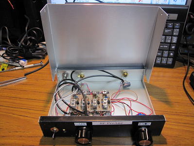
I made the preamp.
ある晩、14MHzをワッチしていたら、ノイズは少なく、ノイズによるsメータも振れない。
DX局のSの振れも少ない。
受信信号の絶対量が少なく、トランシーバのプリアンプだけでは不足だと思った。
ノイズが多い状態でプリアンプを使うと、ノイズ増幅機になってしまうが、
このような場合こそ、プリアンプが有効だと思い、プリアンプを作ってみました。
I selected Fcz Preamp.
Because the band-pass filter has adhered, only a target signal is amplified.
Fcz研究所のプリアンプを使用してみました。
なぜなら、バンドパスフィルタが付いている為、目的の信号だけを増幅するからです。
Block
diagram
Relay
The relay of the input and the relay of the output are different.
入力のリレーと出力のリレーは別にする。離す。
(発信防止)
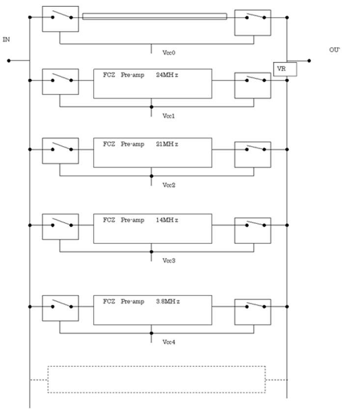
Rotary Switch for band switch
Preamp
circuit diagram
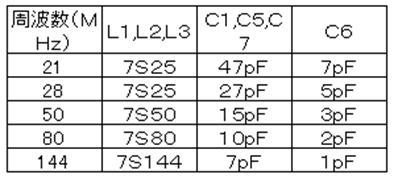
Coil data of fcz pre-amp kit
FCZプリアンプキットのLとCもデータ
 」」
」」
The kit is 21MHz and 28MHzonly.(HFBAND).
But it is possible according to the change of the coil and the condenser.
HF帯のキットは、21MHzと28MHzだけでした。
他のバンドは、コイルとコンデンサを変更すると可能になると思われます。
DATA of FCZ coil data sheet
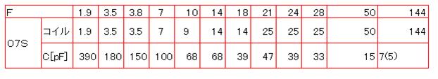
The description is not in the value of C6.
I calculated the value of C6 by the proportion calculation. 、
C6の値は、なし。
C6の値は、比例計算で求めた。
28MHz 5pF 144MHz 1p
↓
14MHz is twice 28MHz → 5pF×2=10pF
14MHz is ten times 144MHz → 1pF×10=10pF
24MHz 6pF
14MHz 10pF
3.5MHz 40pF
Adjustment
(1) Connect with the antenna and transceiver.
(2)Adjustment of L1 (Center of frequency S-metter max)
(3)Adjustment of L12 (1/4 under frequency S-metter max)
(4)Adjustment of L13 (1/4 upper frequency S-metter max)
Repeat from(2) to
(4)
These are
described to the manual of the kit.
I have a
question.
1/4 under frequency? 1/4 upper frequency?
Maybe, I think
as it is an example.
Example:
Case of Bandwidth of frequency 21.150MHz〜21.350MHz
Center of frequency:21.250MHz
1/4 under frequency:21.175MHz
21.250MHz−21.150MHz=0.100MHz
0.100MHz×1/4=0.025MHz
21.150MHz+0.025MHz
1/4 upper frequency:21.325MHz
It
calculates similarly.
調整
1)GaAs RFプリアンプに12Vの電源をつなぎ、入力にアンテナ、出力を受信機につなぎます。
(2)希望周波数の中央周波数で感度が最大になるようにL1を調整します。この時受信する信号はなるべく弱い信号にしてください。
(3)同じ信号で L2,L3を調整すれば感度、混変調特性が最高になります。
(4)これらの特性を若干犠牲にして L2,L3をずらすことによって使用する帯域を広くする事ができます。その方法は……
(5)希望周波数の下から 1/4の周波数にL2を調整します。
(6)希望周波数の上から 1/4の周波数にL3を調整します。
(7)(5),(6)の操作を数回繰り返します。
Sense of use 使用感
When the noise level is a little,
it is effective in the signal to which the signal strength meter doesn't swing.
ノイズでSメータが振れていない時、
Sメータがほとんど振れない信号に対して効果があるような気がします。
Now 3.8/14/21/24MHz。
I would like to add another band. In the near future
近い将来、別のバンドも追加したい。